Converting Wii's Bluetooth module to a USB dongle
Original thread on Dolphin forums
This page assumes no previous soldering knowledge whatsoever.
If you want perfect connection of real Wii motes to the Dolphin emulator, you want to pass-through one of the original chips to Dolphin.
There are two chips, the older 4250A-WML-C43 and the newer J27H002. The only difference between those seems to be that the newer version has slightly smaller test pads, but they're pretty small on both versions, so it's not going to make your job too much easier by choosing one over the other.
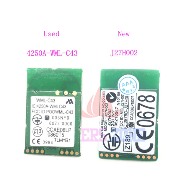
Both chips go for about $1.3 a pop on Aliexpress.
List of things you'll need for this -
- BT chip ($1.3)
- Multimeter ($22.5) - Optional, but highly encouraged to save your sanity
- 6cm Black and Red wires ($0.8) - Ideally get black, red, white and green.
- Soldering iron ($5)
- Soldering stand with sponge ($1.8)
- 0.6mm solder wire ($1.6)
- Shrink tubes ($2)
- LD1117V33 Voltage regulator ($2.5)
- USB-A connector ($1)
- Solder flux ($2)
- Third Hand ($5.7) - Optional but it'll make your life easier
- Glue gun, or electrical tape if you don't have one
- (The links are bound to die sooner or later, use the URL name to find equivalent)
When you're done and you get the USB dongle to show up when connected, follow the Bluetooth Passthrough wiki page.
I will not be wiring the sync button as you can just use the software button in Dolphin when connecting the Wii motes, so essentially just ignore the button on the following schematic. If you want it there you're free to wire it up of course.
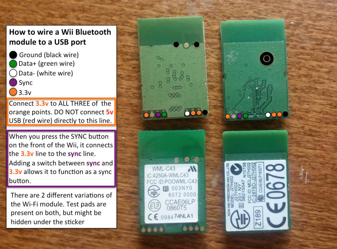
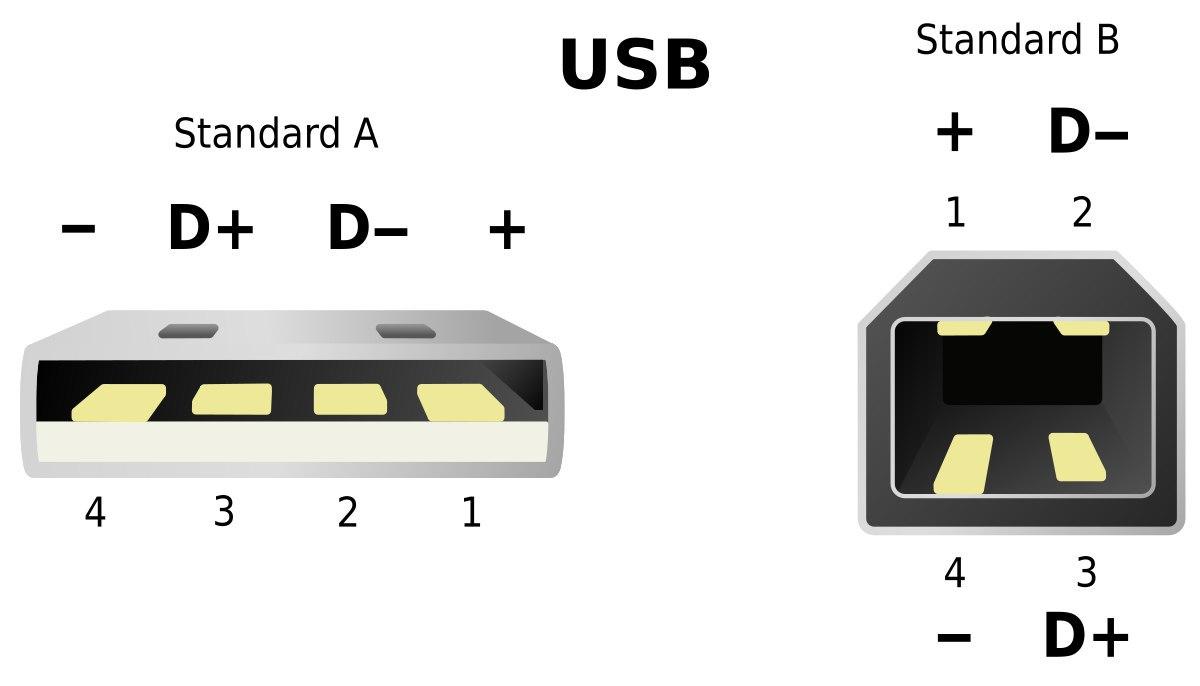
- Solder the 4 wires to the USB-A connector and pull the cables through the plastic cover. Red for +, black for -, green for Data+ and white for Data-
- Continuity test - make sure none of the 4 pins is connected to its nearby pin(s) and that all pins are connected to the wires
- Pull the plastic cover onto the USB connector hard so it stays in place
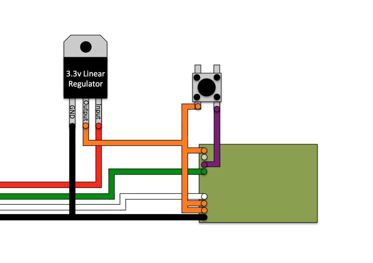
- Put a shrink tube on USB(-) and pull another black wire through it, solder both to regulator GND. You should twist the wire ends together when soldering two at the same time
- Take two red wires and solder them to regulator output, put a shrink tube on them
- Put a shrink tube on USB(+) red wire and solder the wire to regulator input
- Continuity test the 2 pairs of wires on the regulator
- Pull the shrink tubes up and heat them under fire
- If you're using liquid flux like I am, pour it on the pads , let it be the for a short while then dry it up (or don't dry it if your flux doesn't turn into charcoal when heated up like mine does)
- If you don't have properly colored wires for Data+ and -, tontinuity test which wire is which and solder them onto the BT chip
- The 2 output red wires are because there's 3 output pads total (orange) - you need to connect all 3 together. One wire goes to the singular left pad, and other wire goes between the 2 right pads and you bridge those together
- Solder the remaining GND and you're done soldering
- Clean your iron on the damp sponge, put some solder on the tip and turn it off. this prevents degrading the tip.
- Test the dongle you made in a computer
- Finally hot glue the connections on the BT chip so they don't come off in case they get tugged on hard
- Put the connector on the USB dongle and hot glue it, hot glue the regulator from the other side
- With a working adapter, follow Dolphin's BT passthrough page